

Electric Motors
In an earlier concept, we described and calculated the force that a magnetic field exerts on a current carrying wire. Since you are familiar with Newton’s third law of motion, you know that if the magnetic field exerts a force on the current carrying wire, then the current carrying wire also exerts a force of equal magnitude and opposite direction on the magnetic field.
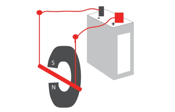
In the sketch above, a circuit is connected to a battery, with one part of the circuit placed inside a magnetic field. When current runs through the circuit, a force will be exerted on the wire by the magnetic field, causing the wire to move. If we choose to consider electron current in this case, the electrons flow from the back of the sketch to the front while the magnetic field is directed upward. Using the left hand rule for this, we find that the force on the wire is to the right of the page. Had we chosen to consider the current to be conventional current, then the current would be flowing from the front of the sketch to the back and we would use the right hand rule. The force on the wire would, once again, be toward the right. This movement is harnessed in
Electrical motors change electrical energy into mechanical energy. The motor consists of an electrical circuit with part of the wires inside a magnetic field. This can be seen below. Positive charges move through the circuit in the direction of the light purple arrows. When the charges move up through the part of the coil that is right next to the north pole, the right hand rule tells us that the wire suffers the force, F, pushing the wire in the direction of the blue arrow, toward the back of the sketch. On the other side of the coil, where the charges are moving down through the field, the right hand rule shows the force would push this side of the coil toward the front. These two forces are working together, rotating the coil in the direction of the circular red arrow.

Where the rotating coil (in grey) meets the wires attached to the power source (black), we find a split ring commutator. The coil turns, but the commutator and power source do not. As the coil turns, it moves off of the blue box connector and as it continues to turn, it connects to the other blue box connector. As the coil turns, it reverses its connections to the external circuit. Therefore, inside the coil, the current is always flowing in the same direction because the left side of the coil is always attached to the left side of the external circuit. This allows the coil, or armature, to continue to spin the same direction all the time.
In electrical motors, these coils often consist of not just one, but many wires, as can be seen here:

Launch the Electric Motor simulation below to visualize how we convert electrical energy into mechanical energy to create a motor. When experimenting with the simulation, you can manipulate the size of the motor, the strength of the input current, the strength of the magnetic field, and the number of turns in the wire.
Summary
- When current runs through the circuit, a force will be exerted on the wire.
- An electrical motor changes electrical energy into mechanical energy.
- A split ring commutator keeps the current in the coil flowing in the same direction even though the coil changes sides every half turn.
Review
1. Which way will the wire be pushed when current passes through the wire?
- up
- down
- left
- right
- None of these.

2. Which way will the coil spin when current passes through the wire?
- clockwise
- counterclockwise

Electric Motor related experiment:-